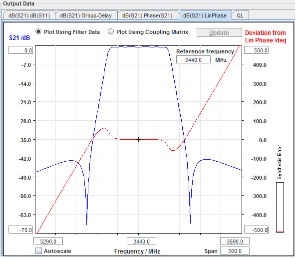
| Output Section - Graphs - Deviation From Linear Phase |
|
| Output Section - Graphs - Deviation From Linear Phase |
|
|
|
| Many electrical
or electronic devices will delay some frequencies more than others,
creating non-linear phase-shift (distortion in signals consisting of
multiple-frequency components). Measuring deviation from linear phase is a
way to quantify this non-linear phase shift.
The deviation from linear phase presents data in units of phase rather than units of seconds (group delay). For devices that pass modulated signals, units of phase may be most practical. |
|
Since it is only the deviation from linear
phase which causes phase distortion, the linear portion of the phase
response is removed from the simulation. The frequency where this is done is the reference frequency, which per default is the center frequency of the filter, but any frequency within the simulated frequency span can be specified. The reference frequency is entered in the text box inside the plot. Calculation of the deviation from linear phase at this frequency is initiated by hitting the "Return" key of your keyboard (not the "Calculate" button in CMS). |
|
|
| The reference frequency is marked by a ring on the phase curve. The phase deviation at this point is per definition zero. |
© 2017, Guided Wave Technology - All Rights Reserved