| Input Section - Topology Matrix |
|
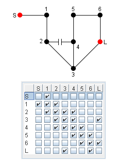
| The
topology matrix describes which couplings the filter designer will allow
in a filter, and which he will not allow. In this way the filter
designer can define the "shape" - or topology - of the
physical filter.
For example - wheater input and output connectors are placed in the same end - or opposite - is defined by the topology matrix (see examples below). Boxes where couplings are allowed
must be 'Checked'. Empty boxes correspond to zero coupling between involved
elements. |
|
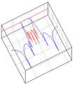
| The matrix
synthesizer tries to make an identical match of the desired
characteristic. If e.g. two transmission zeroes are specified the
synthesis will only be characterized as 'successful' if a topology is
specified which generates exactly two zeroes. A three zeroes
characteristic would be characterized as a 'failure' even though the
rejection performance might even be better.
The best is of course to specify a
topology which is known to be able to match the desired characteristic. |
|
| Topology Matrix Examples: |
|
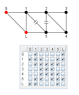
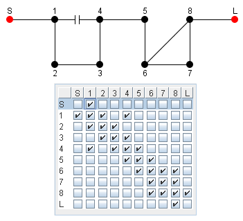
| Fully canonical folded form | Quadruplet and triplet in series |
 |
 |
|
|
|
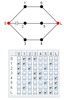
| Parallel topology |
Another topology |
 |
 |
|
Some background: |
|
|
The folded form is used as
default in this software but even though this form is an often used
topology in real microwave filters other forms may be more practical for
a given application. |
|
|
More information may also be found in [4] |
|