|
|
|
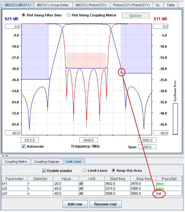
| Restricted areas in the
filter characteristic may be shown either by use of limit lines or
keep-out areas.
|
|
|
| Lines or areas showing the limits of
the filter characteristic can be defined and shown together with the
S-parameter plots. |
| This feature gives a fast
overview of the filter performance relative to the specifications of the
filter. |
| |
- Filter masks are easily defined or
removed in the 'Limit Lines' pane below the S-parameter plot area.
- An unlimited number of masks/lines may
be defined
- Limit lines are only available in the
'dB(S21) dB(S11)' pane
- A pass/fail indicator is attached to
each limit, which gives an instant status of the filter
characteristic relative to the requirements.
- The pass/fail indicators are only
dealing with the part of the characteristic, which is visible within
the plot window.
Limits which have a start or stop frequency that falls outside the
plot window, will therefore be assigned a grey 'pass' color, which is
a warning about that the characteristic may not be passing outside the
plot window.
|
The procedure for defining
limits is:
- Click the 'Add row' button. This
inserts an empty row.
- Click in the empty 'Parameter' cell
and select the S-parameter, which the limit line is tied to.
- Click in the empty 'Selector' cell and
chose either the 'above' (>) or 'below' (<) operator.
- Fill out the level value (dB) and the
frequency range, which the line has to cover.
The line now becomes visible in the plot.
|
|

|
| |
|
Hints: When a row in the table
is selected by the mouse, the corresponding limit line is
emphasized.
The shading of a row may be cleared by pressing 'Add row' and then 'Remove
row'.
|