| Output Section - Coupling Diagram |
|
| Output Section - Coupling Diagram |
|
|
|
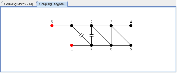
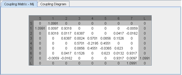
| The Coupling
Matrix can also be depicted as a circuit diagram, which shows all
couplings, I/O ports and resonators in the filter. Positive (inductive) couplings are shown as solid lines. Negative (capacitive) couplings with a capacitor symbol. |
| This diagram
representation of the coupling matrix gives a better overview of the
filter topology.
Not all coupling matrices may be depicted as a simple circuit. CMS recognices commonly appearing topologies as: Folded, meander, zig-zag etc. If a topology can not be recognized a message is displayed instead. |
|
|
|
|
| Further information about coupling matrices can be found here. |
© 2017, Guided Wave Technology - All Rights Reserved